 So what do you do with an old flash with no manual power control? You modify it of course.
Not such a big deal if the flash in question has an Auto mode sensor, just replace the sensor with a logrithmic pot. But if it is a TTL only flash then you have a lot more work.
In 1990 Canon released a small hotshoe mount flash the 200E. As bare bones as you can get. Controlled by A-TTL only.
It has a power switch to turn it on and a ready light to tell you when it was (you guessed it) ready to fire. Nothing else for controls. It doesn't even have a test button.
While it can be used on an old A-TTL film camera but it is next to useless for off camera work. So I changed by adding manual power control, adding a test button, and an optical slave circuit. Still to come is a 1/8" jacj so it can be triggered by an RF or external optical trigger. As soon as I decide where to put it.
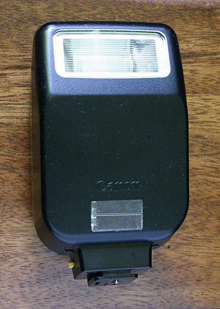
The top image is the front view of a modified Canon 200E flash. The focus assist light was removed and a solar cell used for optical triggering (and other parts) were added. The small yellow pin on the lower left is the new test switch.
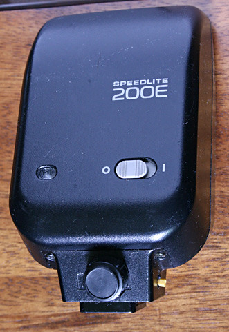
 Bottom rear view of the modified flash. Since I removed the hotshoe pins to fit the new parts this flash can never be triggered by a hotshoe connection again. It can be triggered by the added optical slave trigger or the 1/8" (3.5mm) jack once I figure out where I want to put it. And as a test it can be triggered by the new test switch.
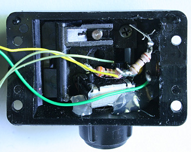 The base had the hotshoe pins removed and some of the plastic milled out to make room for a power control pot and a test switch.
I was careful to retain the hotshoe locking mechanism and locking pin. Made for a tight fit but a necessity. The two one of the resistors shown is conected in series with the power control pot, the other is connected across a capacitor and both in series with the small test swich. A little hot melt glue holds it all in place.
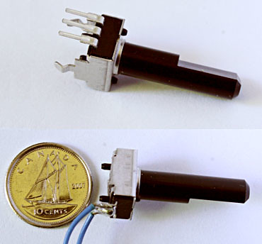 I had been using some full sized pots for doing modifications to Auto controlled flashes. I was using log pots sold for electric guitar volume controls. I was not happy with this so I kept looking for something smaller. I came up with the pot on the left. It is not much bigger than a trimmer pot, with the addition of a full size shaft. It was near perfect for my application. The dime is to give you a sense of size.
I cut off the mounting tabs and the pot connection I didn't plan on using. (Measure twice and cut once. Make sure you cut off the right one.) Then solder a couple of fine wires that will go back to the control board. I also cut down the shaft so it would stick through the case and have enough length for a small knob.
 Now for the the control circuit. As I said above adding power control on an old Auto exposure flash is relatively easy. All you do in most cases is swap a variable resistor for the sensor. All the timing is handled by the existing circuitry. For a TTL flash with no Auto mode you have to generate the shutoff/quench control signals yourself. And that is what the circuit to the left (schematic below) does.
I have previously made a version of this circuit using a point to point wiring technique. No circuit board. Just solder the parts to the chip and keep adding parts and wires until you are done. All was done with regular through hole parts (bigger). I modified a Canon TTL version of a Sunpack 355AF flash this way. An OK technique if you are just doing one. Since I wanted to be able to do more of these modifications in the future I wanted a circuit board to work from. Much less work.
I was designing a circuit board for a new product at work and I had some free space left over on the board. I decided to add my circuit and piggyback on the run.
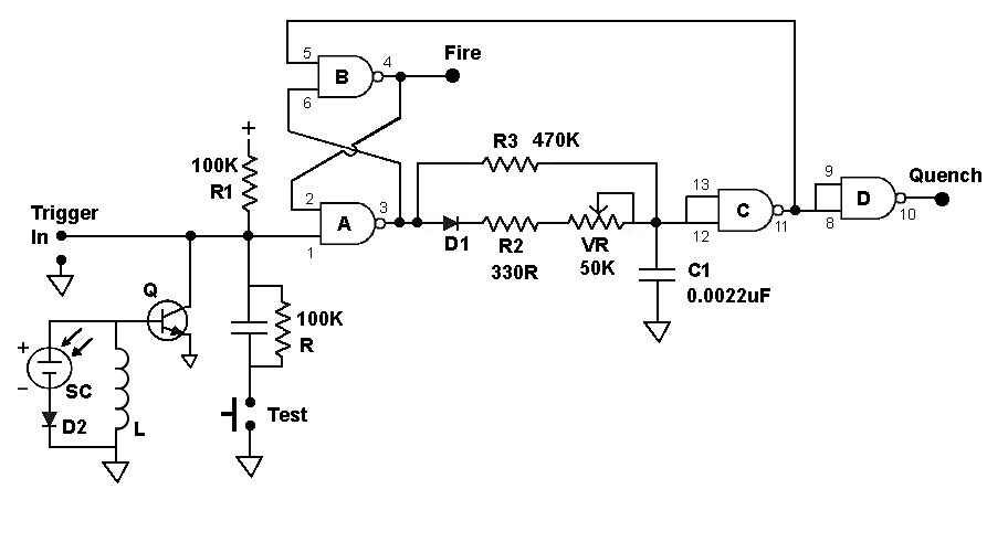
The power connection to the circuit and chip is not shown (for simplicity). All I did was feed the 6 volt battery power through a Schottky diode. A .1uF cap and then this power went to the CMOS 4093 IC. I used a 4093 rather than a 74HC132. The 4093 has a much higher voltage range. While I have used a 74HC132 in my Sunpak 355AF (pictured in the June 2010 entry) the 4093 is a better choice considering the supply voltage. The 74HC132 is really not intended to be used above 5 volts.
The circuit is basically just a latch (gates A & B) with a time delay to reset the latch. From pin 3 to gate C of the chip determines the time delay. Section D just inverts the quench signal for the proper polarity for Canon flashes.
Hi Rudy,
ReplyDeleteCan you tell me wich pin on the flash shoe is the "quench" pin ?
Best regards.
Jerome
Hi Jerome,
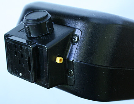
ReplyDeleteLooking at the flash connections with the Fire pin at the 6 o'clock position. The Quench pin is the left pin at 8 o'clock.
X.X
Q.X
.X.
Bottom view.
Thank you very much !
ReplyDeleteOne more question: some capacitor values are missing in your drawing.
Could you please add them ?
Thank you in advance.
You've done good work !
The capacitor (in parallel with the 100K resistor marked R) can be a wide range of values. It's not critical. A good small easy to work with value would be 0.1uF. That's what I used.
ReplyDeleteWhat that cap does is allows the switch to cause a momentary short to the input to trigger the circuit.
All the other capacitors are marked. The part marked SC is not a capacitor but a solar cell I took out of a solar powered calculator I had that stopped working.
I'm not really happy with the solar cell sensitivity. It does work but I hoped for better. If you don't include the solar cell part then you can leave out Q, L, & D2. Just use the external trigger input.
The resistor marked R (100K) probably should be a larger value compared to R1 the 100K resistor above it. Or R1 could be smaller, say 47K. It's not a real problem but that resistor ratio would have been a better choice. Or larger, R could go up to 1M but the 100K is what I used at the time.
Hi Rudy,
ReplyDeleteI finally just started with this circuit fro the modification of a Canon ML-3 TTL only ring flash but I meet some "troubles". So I have some question for you to help me finding what's wrong with my circuit.
1)From your drawing: "Fire" is connected to the fire pin of the hotshoe. Right ? "Trigger" is connected to the wire that is normally connected to the fire pin. Right ?
2)I have taken the power supply directly on the PCB from the flash > +6v and ground. Is it right to take the ground there or is it better to take it on the hotshoe ?
3)My camera does not want to fire the flash once the circuit connected... :( If even tried with short-circuiting the ground and fire pins on the hotshoe > no flash firing :(
Thank you in advance for the help you could provide :)
Jerome
This comment has been removed by the author.
ReplyDeleteHi,
ReplyDeleteI've finally found what I was looking for! Canon Attl pinout !
On a side note, your schematic is really nice. I know it's been a while and I mostly hope you'll get this msg somehow, but do you have any of those PCB left? I'm about to do it point-to-point, but the space I have in my Vivitar 6000AF hot shoe is really small. I could probably fit it inside the flash itself, but i'd prefer to avoid that.
Anyway if you can poke me on google plus or reply to this post that would be really nice.
Thanks again for the info on the TTL pinout and delay circuit.
For Google search : ATTL pinout A-ttl pinout Canon old ttl pinout
Canon Advance ttl pinout.